 The motorcycle* helmet foam liner is made of two density layers. The outer layer, which is the black part, is made of high density foam and has truncated cones facing inwards. The inner layer, the grey part which is close to the head, is made of softer low density foam and has cones facing outwards where the apices of the cones are contiguous with the outer surface,
In the above diagram compression refers to when the cross-section of the foam liner is subjected to an impact force. The impact force, as indicated by the downward arrow, is pushing towards the head and causes the tops of the lower density cones (the grey cones) to compress. The collapsing of the cones causes the energy to spread (laterally) sideways within the thickness of the foam liner instead of towards the head. The dispersion of the energy sideways prevents the impact energy to be translated through to the brain
At the same time, the head is traveling in the opposite direction, as indicated by the arrow pointing upwards. You may recall this as Newton’s third law of motion – equal and opposite forces. As a result, the head causes the bases of low density foam cones to compress. Also, the fact that the head is continually pushing into higher density foam allows the head to gradually slow down or other words gradually decelerate. The result is a lower g-force to your head.
The true benefits of the new motorcycle* helmets incorporating the ![]() technology are:
technology are:
- a softer liner whereby the cones play a very important part to help to manage or absorb an impact force more efficiently
- a lighter helmet that helps to reduce rotational acceleration of the head during impact, and
- a softer liner close to one’s head to lower g-forces
* The same ![]() technology applies to motocross, equestrian, snow and skiing helmets.
technology applies to motocross, equestrian, snow and skiing helmets.
The following photos (1 to 3) show the outcome of three different ![]() technology motorcycle helmets after being subjected to an impacting force.
technology motorcycle helmets after being subjected to an impacting force.
Photo 1:
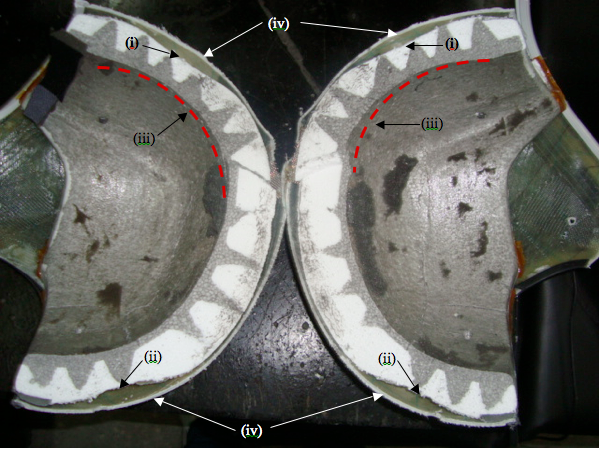
Photo 1 shows a motorcycle helmet, incorporating ![]() technology, cut into halves revealing the cross-section of the inner and outer foam layers and the fibre-glass outer shell. The motorcycle helmet was tested to the 2010 Snell Standard. The test involves dropping a helmet, which has a headform inside the helmet, onto a hemispherical steel anvil.
technology, cut into halves revealing the cross-section of the inner and outer foam layers and the fibre-glass outer shell. The motorcycle helmet was tested to the 2010 Snell Standard. The test involves dropping a helmet, which has a headform inside the helmet, onto a hemispherical steel anvil.
The arrows left rear (i), right rear (i), left front (ii) and right front (ii) show the result of compression to the tops of the low density cones and the outer foam layer of high density under the flexible fibre-glass outer shell (iv). The compression of the low density cones spreads the energy sideways throughout the foam liner instead of towards the head.
The arrows (iii) show compression to the bases of the soft low density cones of the inner foam layer caused by the head-form impacting against the inner foam layer. The approximate outline of the test head form is shown by the red dashed lines.
It can be observed there is a decrease in the thickness of the inner layer in several areas where the cones emanate. This decrease in thickness is the result of the head-form compressing the inner foam layer thereby reducing the g -force.
Photo 2:
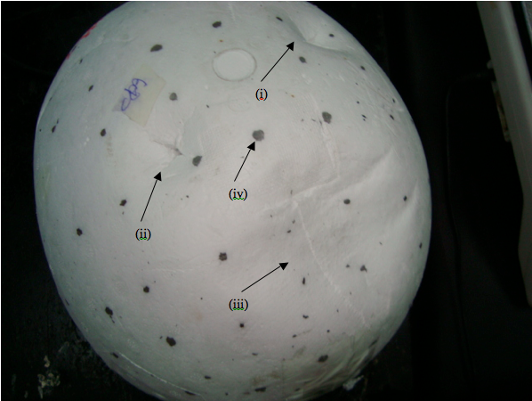
Photo 2 shows a view of the outer foam layer of a ![]() technology motorcycle helmet after being subjected to an impact force (2010 Snell Standard). The
technology motorcycle helmet after being subjected to an impact force (2010 Snell Standard). The ![]() foam liner has been removed from its fibre-glass outer shell.
foam liner has been removed from its fibre-glass outer shell.
The outer foam layer shows three distinct areas of compressions located at (i) right front, (ii) left front and (iii) top. The two areas of compressions at the front (i) and (ii) are from the penetration tests. The black dots (iv) are the apices of the low density cones of the inner layer contiguous with the outer surface of the high density outer layer.
The compression (iii) at the top is from dropping the helmet onto a hemispherical anvil for a peak deceleration test. The degree of compression observed for the helmet is considerably more than that is observed for a single density helmet. The compression indicates the impact energy/force has been spread sideways within the thickness of the foam liner away from the head.
Photo 3:
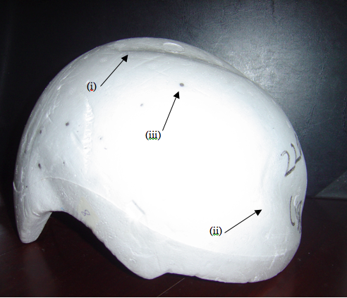
Photo 3 shows a view of the outer foam layer of another ![]() technology motorcycle helmet after being subjected to an impact force (ECE 22.05 Standard).
technology motorcycle helmet after being subjected to an impact force (ECE 22.05 Standard).
Once again the ![]() foam liner has been removed from its fibre-glass outer shell and shows two distinct areas of compression at (i) and (ii). The two compressions are the result of the impact energy/force spread sideways (laterally) within the thickness of the
foam liner has been removed from its fibre-glass outer shell and shows two distinct areas of compression at (i) and (ii). The two compressions are the result of the impact energy/force spread sideways (laterally) within the thickness of the ![]() foam liner. The black dots (iii) are the apices of the low density foam cones contiguous with the outer surface of the high density outer foam layer.
foam liner. The black dots (iii) are the apices of the low density foam cones contiguous with the outer surface of the high density outer foam layer.
“Wearing a certified approved and properly fitting helmet can mean the difference between life and death.”
~ Don Morgan
